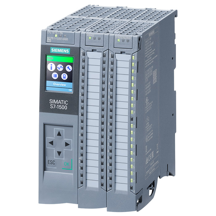
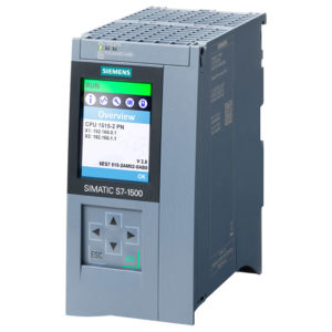
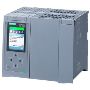
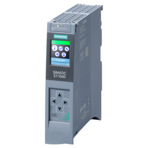
6ES7511-1CK01-0AB0 là bộ điều khiển khả trình logic (PLC) nâng cao do hãng SIEMENS sản xuất và phát triển với thương hiệu SIMATIC thuộc dòng PLC S7-1500. Bộ điều khiển lập trình SIMATIC S7-1500 CPU 1511C-1PN 6ES7511-1CK01-0AB0 được Công ty Cổ Phần UNATRO phát triển và phân phối rộng rãi trên thị trường Việt Nam. Nếu quý khách hàng đang có nhu cầu cần tư vấn hay mua bộ điều khiển CPU 1511C-1PN 6ES7511-1CK01-0AB0 thì hãy liên hệ UNATRO.COM để được hỗ trợ một cách tận tâm, nhanh chóng và hiệu quả nhé.
Tổng quan về CPU 1511C-1PN 6ES7511-1CK01-0AB0
Mô tả tóm tắt bằng tiếng Việt: Bộ điều khiển lập trình SIMATIC S7-1500, CPU nhỏ gọn, CPU 1511C-1PN, Bộ nhớ: 175 KB cho chương trình và 1 MB cho dữ liệu, 16 đầu vào số, 16 đầu ra số, 5 đầu vào tương tự, 2 đầu ra tương tự, 6 bộ đếm xung tốc độ cao (HSC), 4 đầu ra xung tốc độ cao (HSO) cho đầu ra PTO/ PWM/ Frequency, giao diện: PROFINET IRT với 2 cổng chuyển mạch, hiệu suất bit 60 NS, bao gồm đầu nối push-in, cần thêm thẻ nhớ SIMATIC để hoạt động.
Mô tả tóm tắt bằng tiếng Anh: SIMATIC S7-1500 Compact CPU, CPU 1511C-1PN, central processing unit with working memory 175 KB for program and 1 MB for data, 16 digital inputs, 16 digital outputs, 5 analog inputs, 2 analog outputs, 6 high speed counters, 4 high speed outputs for PTO/PWM/frequency output 1. interface: PROFINET IRT with 2 port switch, 60 NS bit-performance, incl. front connector push-in, SIMATIC memory card necessary.
Bảng tóm tắt thông số kỹ thuật CPU 1511C-1PN 6ES7511-1CK01-0AB0
| Mã sản phẩm | 6ES7511-1CK01-0AB0 |
| Dòng sản phẩm | SIMATIC S7-1500, Compact CPU, CPU 1511C-1PN |
| Hãng sản xuất | SIEMENS |
| Xuất xứ | China (Trung quốc) / CN |
| Hiệu suất bit | 60 ns |
| Giao diện | PROFINET IRT |
| Bộ nhớ | 175 KB chương trình và 1 MB dữ liệu |
| Số lượng đầu vào số | 16 DI (6 HSC) |
| Số lượng đầu ra số | 16 DO (4 HSO) |
| Số lượng đầu vào tương tự | 5 AI |
| Số lượng đầu ra tương tự | 2 AO |
| Nguồn cung cấp | 24 V DC (19.2-28.8 V DC) |
| Kích thước (Rộng x Cao x Sâu) | 85 x 147 x 129 mm |
| Trọng lượng | 1 050 g |
Bảng chi tiết thông số kỹ thuật CPU 1511C-1PN 6ES7511-1CK01-0AB0
| Article number | 6ES7511-1CK01-0AB0
CPU 1511C-1 PN, 175 KB Prog, 1 MB Data |
| General information | |
| Product type designation | CPU 1511C-1 PN |
| HW functional status | FS03 |
| Firmware version | V2.9 |
| Product function | |
| ● I&M data | Yes; I&M0 to I&M3 |
| ● Isochronous mode | Yes; With minimum OB 6x cycle of 625 µs (distributed) |
| Engineering with | |
| ● STEP 7 TIA Portal configurable/ integrated from version | V17 (FW V2.9) / V15 (FW V2.5) or higher; with older TIA Portal versions configurable as 6ES7511-1CK00-0AB0 |
| Configuration control | |
| via dataset | Yes |
| Display | |
| Screen diagonal [cm] | 3.45 cm |
| Control elements | |
| Number of keys | 8 |
| Mode buttons | 2 |
| Supply voltage | |
| Type of supply voltage | 24 V DC |
| permissible range, lower limit (DC) | 19.2 V; 20.4 V DC, for supplying the digital inputs/ outputs |
| permissible range, upper limit (DC) | 28.8 V |
| Reverse polarity protection | Yes |
| Mains buffering | |
| ● Mains/voltage failure stored energy time | 5 ms; Refers to the power supply on the CPU section |
| ● Repeat rate, min. | 1/s |
| Input current | |
| Current consumption (rated value) | 0.8 A; Without load; 9.8 A: CPU + load |
| Current consumption, max. | 1 A; Without load; 10 A: CPU + load |
| Inrush current, max. | 1.9 A; Rated value |
| I²t | 0.34 A²·s |
| Digital inputs | |
| ● from load voltage L+ (without load), max. | 20 mA; per group |
| Digital outputs | |
| ● from load voltage L+, max. | 30 mA; Per group, without load |
| output voltage / header | |
| Rated value (DC) | 24 V |
| Encoder supply | |
| Number of outputs | 1; One common 24 V encoder supply |
| 24 V encoder supply | |
| ● 24 V | Yes; L+ (-0.8 V) |
| ● Short-circuit protection | Yes |
| ● Output current, max. | 1 A |
| Power | |
| Infeed power to the backplane bus | 10 W |
| Power consumption from the backplane bus (balanced) | 8.5 W |
| Power loss | |
| Power loss, typ. | 11.8 W |
| Memory | |
| Number of slots for SIMATIC memory card | 1 |
| SIMATIC memory card required | Yes |
| Work memory | |
| ● integrated (for program) | 175 kbyte |
| ● integrated (for data) | 1 Mbyte |
| Load memory | |
| ● Plug-in (SIMATIC Memory Card), max. | 32 Gbyte |
| Backup | |
| ● maintenance-free | Yes |
| CPU processing times | |
| for bit operations, typ. | 60 ns |
| for word operations, typ. | 72 ns |
| for fixed point arithmetic, typ. | 96 ns |
| for floating point arithmetic, typ. | 384 ns |
| CPU-blocks | |
| Number of elements (total) | 4 000; Blocks (OB, FB, FC, DB) and UDTs |
| DB | |
| ● Number range | 1 … 60 999; subdivided into: number range that can be used by the user: 1 … 59 999, and number range of DBs created via SFC 86: 60 000 … 60 999 |
| ● Size, max. | 1 Mbyte; For DBs with absolute addressing, the max. size is 64 KB |
| FB | |
| ● Number range | 0 … 65 535 |
| ● Size, max. | 175 kbyte |
| FC | |
| ● Number range | 0 … 65 535 |
| ● Size, max. | 175 kbyte |
| OB | |
| ● Size, max. | 175 kbyte |
| ● Number of free cycle OBs | 100 |
| ● Number of time alarm OBs | 20 |
| ● Number of delay alarm OBs | 20 |
| ● Number of cyclic interrupt OBs | 20; With minimum OB 3x cycle of 500 µs |
| ● Number of process alarm OBs | 50 |
| ● Number of DPV1 alarm OBs | 3 |
| ● Number of isochronous mode OBs | 1 |
| ● Number of technology synchronous alarm OBs | 2 |
| ● Number of startup OBs | 100 |
| ● Number of asynchronous error OBs | 4 |
| ● Number of synchronous error OBs | 2 |
| ● Number of diagnostic alarm OBs | 1 |
| Nesting depth | |
| ● per priority class | 24 |
| Counters, timers and their retentivity | |
| S7 counter | |
| ● Number | 2 048 |
| Retentivity | |
| — adjustable | Yes |
| IEC counter | |
| ● Number | Any (only limited by the main memory) |
| Retentivity | |
| — adjustable | Yes |
| S7 times | |
| ● Number | 2 048 |
| Retentivity | |
| — adjustable | Yes |
| IEC timer | |
| ● Number | Any (only limited by the main memory) |
| Retentivity | |
| — adjustable | Yes |
| Data areas and their retentivity | |
| Retentive data area (incl. timers, counters, flags), max. | 128 kbyte; In total; available retentive memory for bit memories, timers, counters, DBs, and technology data (axes): 88 KB |
| Extended retentive data area (incl. timers, counters, flags), max. | 1 Mbyte; When using PS 6 0W 24/48/60 V DC HF |
| Flag | |
| ● Size, max. | 16 kbyte |
| ● Number of clock memories | 8; 8 clock memory bit, grouped into one clock memory byte |
| Data blocks | |
| ● Retentivity adjustable | Yes |
| ● Retentivity preset | No |
| Local data | |
| ● per priority class, max. | 64 kbyte; max. 16 KB per block |
| Address area | |
| Number of IO modules | 1 024; max. number of modules / submodules |
| I/O address area | |
| ● Inputs | 32 kbyte; All inputs are in the process image |
| ● Outputs | 32 kbyte; All outputs are in the process image |
| per integrated IO subsystem | |
| — Inputs (volume) | 8 kbyte |
| — Outputs (volume) | 8 kbyte |
| per CM/CP | |
| — Inputs (volume) | 8 kbyte |
| — Outputs (volume) | 8 kbyte |
| Subprocess images | |
| ● Number of subprocess images, max. | 32 |
| Hardware configuration | |
| Number of distributed IO systems | 32; A distributed I/O system is characterized not only by the integration of distributed I/O via PROFINET or PROFIBUS communication modules, but also by the connection of I/O via AS-i master modules or links (e.g. IE/PB-Link) |
| Number of DP masters | |
| ● Via CM | 4; A maximum of 4 CMs/CPs (PROFIBUS, PROFINET, Ethernet) can be inserted in total |
| Number of IO Controllers | |
| ● integrated | 1 |
| ● Via CM | 4; A maximum of 4 CMs/CPs (PROFIBUS, PROFINET, Ethernet) can be inserted in total |
| Rack | |
| ● Modules per rack, max. | 32; CPU + 31 modules |
| ● Number of lines, max. | 1 |
| PtP CM | |
| ● Number of PtP CMs | the number of connectable PtP CMs is only limited by the number of available slots |
| Time of day | |
| Clock | |
| ● Type | Hardware clock |
| ● Backup time | 6 wk; At 40 °C ambient temperature, typically |
| ● Deviation per day, max. | 10 s; Typ.: 2 s |
| Operating hours counter | |
| ● Number | 16 |
| Clock synchronization | |
| ● supported | Yes |
| ● in AS, master | Yes |
| ● in AS, slave | Yes |
| ● on Ethernet via NTP | Yes |
| Digital inputs | |
| integrated channels (DI) | 16 |
| Digital inputs, parameterizable | Yes |
| Source/sink input | P-reading |
| Input characteristic curve in accordance with IEC 61131, type 3 | Yes |
| Digital input functions, parameterizable | |
| ● Gate start/stop | Yes |
| ● Capture | Yes |
| ● Synchronization | Yes |
| Input voltage | |
| ● Type of input voltage | DC |
| ● Rated value (DC) | 24 V |
| ● for signal “0” | -3 to +5V |
| ● for signal “1” | +11 to +30V |
| Input current | |
| ● for signal “1”, typ. | 2.5 mA |
| Input delay (for rated value of input voltage) | |
| for standard inputs | |
| — parameterizable | Yes; none / 0.05 / 0.1 / 0.4 / 1.6 / 3.2 / 12.8 / 20 ms |
| — at “0” to “1”, min. | 4 µs; for parameterization “none” |
| — at “0” to “1”, max. | 20 ms |
| — at “1” to “0”, min. | 4 µs; for parameterization “none” |
| — at “1” to “0”, max. | 20 ms |
| for interrupt inputs | |
| — parameterizable | Yes; Same as for standard inputs |
| for technological functions | |
| — parameterizable | Yes; Same as for standard inputs |
| Cable length | |
| ● shielded, max. | 1 000 m; 600 m for technological functions; depending on input frequency, encoder and cable quality; max. 50 m at 100 kHz |
| ● unshielded, max. | 600 m; for technological functions: No |
| Digital outputs | |
| Type of digital output | Transistor |
| integrated channels (DO) | 16 |
| Current-sourcing | Yes; Push-pull output |
| Short-circuit protection | Yes; electronic/thermal |
| ● Response threshold, typ. | 1.6 A with standard output, 0.5 A with high-speed output; see manual for details |
| Limitation of inductive shutdown voltage to | -0.8 V |
| Controlling a digital input | Yes |
| Accuracy of pulse duration | Up to ±100 ppm ±2 μs at high-speed output; see manual for details |
| minimum pulse duration | 2 µs; With High Speed output |
| Digital output functions, parameterizable | |
| ● Switching tripped by comparison values | Yes; As output signal of a high-speed counter |
| ● PWM output | Yes |
| — Number, max. | 4 |
| — Cycle duration, parameterizable | Yes |
| — ON period, min. | 0 % |
| — ON period, max. | 100 % |
| — Resolution of the duty cycle | 0.0036 %; For S7 analog format, min. 40 ns |
| ● Frequency output | Yes |
| Switching capacity of the outputs | |
| ● with resistive load, max. | 0.5 A; 0.1 A with high-speed output, i.e. when using a high-speed output; see manual for details |
| ● on lamp load, max. | 5 W; 1 W with high-speed output, i.e. when using a high-speed output; see manual for details |
| Load resistance range | |
| ● lower limit | 48 Ω; 240 ohms with high-speed output, i.e. when using a high-speed output; see manual for details |
| ● upper limit | 12 kΩ |
| Output voltage | |
| ● Type of output voltage | DC |
| ● for signal “0”, max. | 1 V; With high-speed output, i.e. when using a high-speed output; see manual for details |
| ● for signal “1”, min. | 23.2 V; L+ (-0.8 V) |
| Output current | |
| ● for signal “1” rated value | 0.5 A; 0.1 A with high-speed output, i.e. when using a high-speed output, observe derating; see manual for details |
| ● for signal “1” permissible range, min. | 2 mA |
| ● for signal “1” permissible range, max. | 0.6 A; 0.12 A with high-speed output, i.e. when using a high-speed output, observe derating; see manual for details |
| ● for signal “0” residual current, max. | 0.5 mA |
| Output delay with resistive load | |
| ● “0” to “1”, max. | 200 µs |
| ● “1” to “0”, max. | 500 µs; Load-dependent |
| for technological functions | |
| — “0” to “1”, max. | 5 µs; Depending on the output used, see additional description in manual |
| — “1” to “0”, max. | 5 µs; Depending on the output used, see additional description in manual |
| Parallel switching of two outputs | |
| ● for logic links | Yes; for technological functions: No |
| ● for uprating | No |
| ● for redundant control of a load | Yes; for technological functions: No |
| Switching frequency | |
| ● with resistive load, max. | 100 kHz; For high-speed output, 100 Hz for standard output |
| ● with inductive load, max. | 0.5 Hz; Acc. to IEC 60947-5-1, DC-13; observe derating curve |
| ● on lamp load, max. | 10 Hz |
| Total current of the outputs | |
| ● Current per channel, max. | 0.5 A; see additional description in the manual |
| ● Current per group, max. | 8 A; see additional description in the manual |
| ● Current per power supply, max. | 4 A; 2 power supplies for each group, current per power supply max. 4 A, see additional description in manual |
| for technological functions | |
| — Current per channel, max. | 0.5 A; see additional description in the manual |
| Relay outputs | |
| ● Number of relay outputs | 0 |
| Cable length | |
| ● shielded, max. | 1 000 m; 600 m for technological functions; depending on output frequency, load, and cable quality; max. 50 m at 100 kHz |
| ● unshielded, max. | 600 m; for technological functions: No |
| Analog inputs | |
| Number of analog inputs | 5; 4x for U/I, 1x for R/RTD |
| ● For current measurement | 4; max. |
| ● For voltage measurement | 4; max. |
| ● For resistance/resistance thermometer measurement | 1 |
| permissible input voltage for voltage input (destruction limit), max. | 28.8 V |
| permissible input current for current input (destruction limit), max. | 40 mA |
| Cycle time (all channels), min. | 1 ms; Dependent on the parameterized interference frequency suppression; for details, see conversion procedure in manual |
| Technical unit for temperature measurement adjustable | Yes; °C/°F/K |
| Input ranges (rated values), voltages | |
| ● 0 to +10 V | Yes; Physical measuring range: ± 10 V |
| — Input resistance (0 to 10 V) | 100 kΩ |
| ● 1 V to 5 V | Yes; Physical measuring range: ± 10 V |
| — Input resistance (1 V to 5 V) | 100 kΩ |
| ● -10 V to +10 V | Yes |
| — Input resistance (-10 V to +10 V) | 100 kΩ |
| ● -5 V to +5 V | Yes; Physical measuring range: ± 10 V |
| — Input resistance (-5 V to +5 V) | 100 kΩ |
| Input ranges (rated values), currents | |
| ● 0 to 20 mA | Yes; Physical measuring range: ± 20 mA |
| — Input resistance (0 to 20 mA) | 50 Ω; Plus approx. 55 ohm for overvoltage protection by PTC |
| ● -20 mA to +20 mA | Yes |
| — Input resistance (-20 mA to +20 mA) | 50 Ω; Plus approx. 55 ohm for overvoltage protection by PTC |
| ● 4 mA to 20 mA | Yes; Physical measuring range: ± 20 mA |
| — Input resistance (4 mA to 20 mA) | 50 Ω; Plus approx. 55 ohm for overvoltage protection by PTC |
| Input ranges (rated values), resistance thermometer | |
| ● Ni 100 | Yes; Standard/climate |
| — Input resistance (Ni 100) | 10 MΩ |
| ● Pt 100 | Yes; Standard/climate |
| — Input resistance (Pt 100) | 10 MΩ |
| Input ranges (rated values), resistors | |
| ● 0 to 150 ohms | Yes; Physical measuring range: 0 … 600 ohms |
| — Input resistance (0 to 150 ohms) | 10 MΩ |
| ● 0 to 300 ohms | Yes; Physical measuring range: 0 … 600 ohms |
| — Input resistance (0 to 300 ohms) | 10 MΩ |
| ● 0 to 600 ohms | Yes |
| — Input resistance (0 to 600 ohms) | 10 MΩ |
| Cable length | |
| ● shielded, max. | 800 m; for U/I, 200 m for R/RTD |
| Analog outputs | |
| integrated channels (AO) | 2 |
| Voltage output, short-circuit protection | Yes |
| Cycle time (all channels), min. | 1 ms; Dependent on the parameterized interference frequency suppression; for details, see conversion procedure in manual |
| Output ranges, voltage | |
| ● 0 to 10 V | Yes |
| ● 1 V to 5 V | Yes |
| ● -10 V to +10 V | Yes |
| Output ranges, current | |
| ● 0 to 20 mA | Yes |
| ● -20 mA to +20 mA | Yes |
| ● 4 mA to 20 mA | Yes |
| Load impedance (in rated range of output) | |
| ● with voltage outputs, min. | 1 kΩ |
| ● with voltage outputs, capacitive load, max. | 100 nF |
| ● with current outputs, max. | 500 Ω |
| ● with current outputs, inductive load, max. | 1 mH |
| Cable length | |
| ● shielded, max. | 200 m |
| Analog value generation for the inputs | |
| Integration and conversion time/resolution per channel | |
| ● Resolution with overrange (bit including sign), max. | 16 bit |
| ● Integration time, parameterizable | Yes; 2.5 / 16.67 / 20 / 100 ms, acts on all channels |
| ● Interference voltage suppression for interference frequency f1 in Hz | 400 / 60 / 50 / 10 |
| Smoothing of measured values | |
| ● parameterizable | Yes |
| ● Step: None | Yes |
| ● Step: low | Yes |
| ● Step: Medium | Yes |
| ● Step: High | Yes |
| Analog value generation for the outputs | |
| Integration and conversion time/resolution per channel | |
| ● Resolution with overrange (bit including sign), max. | 16 bit |
| Settling time | |
| ● for resistive load | 1.5 ms |
| ● for capacitive load | 2.5 ms |
| ● for inductive load | 2.5 ms |
| Encoder | |
| Connection of signal encoders | |
| ● for voltage measurement | Yes |
| ● for current measurement as 4-wire transducer | Yes |
| ● for resistance measurement with two-wire connection | Yes |
| ● for resistance measurement with three-wire connection | Yes |
| ● for resistance measurement with four-wire connection | Yes |
| Connectable encoders | |
| ● 2-wire sensor | Yes |
| — permissible quiescent current (2-wire sensor), max. | 1.5 mA |
| Encoder signals, incremental encoder (asymmetrical) | |
| ● Input voltage | 24 V |
| ● Input frequency, max. | 100 kHz |
| ● Counting frequency, max. | 400 kHz; with quadruple evaluation |
| ● Signal filter, parameterizable | Yes |
| ● Incremental encoder with A/B tracks, 90° phase offset | Yes |
| ● Incremental encoder with A/B tracks, 90° phase offset and zero track | Yes |
| ● pulse encoder | Yes |
| ● pulse encoder with direction | Yes |
| ● pulse encoder with one impulse signal per count direction | Yes |
| Errors/accuracies | |
| Linearity error (relative to input range), (+/-) | 0.1 % |
| Temperature error (relative to input range), (+/-) | 0.005 %/K |
| Crosstalk between the inputs, max. | -60 dB |
| Repeat accuracy in steady state at 25 °C (relative to input range), (+/-) | 0.05 % |
| Output ripple (relative to output range, bandwidth 0 to 50 kHz), (+/-) | 0.02 % |
| Linearity error (relative to output range), (+/-) | 0.15 % |
| Temperature error (relative to output range), (+/-) | 0.005 %/K |
| Crosstalk between the outputs, max. | -80 dB |
| Repeat accuracy in steady state at 25 °C (relative to output range), (+/-) | 0.05 % |
| Operational error limit in overall temperature range | |
| ● Voltage, relative to input range, (+/-) | 0.3 % |
| ● Current, relative to input range, (+/-) | 0.3 % |
| ● Resistance, relative to input range, (+/-) | 0.3 % |
| ● Resistance thermometer, relative to input range, (+/-) | Pt100 Standard: ±2 K, Pt100 Climate: ±1 K, Ni100 Standard: ±1.2 K, Ni100 Climate: ±1 K |
| ● Voltage, relative to output range, (+/-) | 0.3 % |
| ● Current, relative to output range, (+/-) | 0.3 % |
| Basic error limit (operational limit at 25 °C) | |
| ● Voltage, relative to input range, (+/-) | 0.2 % |
| ● Current, relative to input range, (+/-) | 0.2 % |
| ● Resistance, relative to input range, (+/-) | 0.2 % |
| ● Resistance thermometer, relative to input range, (+/-) | Pt100 Standard: ±1 K, Pt100 Climate: ±0.5 K, Ni100 Standard: ±0.6 K, Ni100 Climate: ±0.5 K |
| ● Voltage, relative to output range, (+/-) | 0.2 % |
| ● Current, relative to output range, (+/-) | 0.2 % |
| Interference voltage suppression for f = n x (f1 +/- 1 %), f1 = interference frequency | |
| ● Series mode interference (peak value of interference < rated value of input range), min. | 30 dB |
| ● Common mode voltage, max. | 10 V |
| ● Common mode interference, min. | 60 dB; at 400 Hz: 50 dB |
| Interfaces | |
| Number of PROFINET interfaces | 1 |
| 1. Interface | |
| Interface types | |
| ● RJ 45 (Ethernet) | Yes; X1 |
| ● Number of ports | 2 |
| ● integrated switch | Yes |
| Protocols | |
| ● IP protocol | Yes; IPv4 |
| ● PROFINET IO Controller | Yes |
| ● PROFINET IO Device | Yes |
| ● SIMATIC communication | Yes |
| ● Open IE communication | Yes; Optionally also encrypted |
| ● Web server | Yes |
| ● Media redundancy | Yes |
| PROFINET IO Controller | |
| Services | |
| — PG/OP communication | Yes |
| — Isochronous mode | Yes |
| — Direct data exchange | Yes; Requirement: IRT and isochronous mode (MRPD optional) |
| — IRT | Yes |
| — PROFIenergy | Yes; per user program |
| — Prioritized startup | Yes; Max. 32 PROFINET devices |
| — Number of connectable IO Devices, max. | 128; In total, up to 256 distributed I/O devices can be connected via AS-i, PROFIBUS or PROFINET |
| — Of which IO devices with IRT, max. | 64 |
| — Number of connectable IO Devices for RT, max. | 128 |
| — of which in line, max. | 128 |
| — Number of IO Devices that can be simultaneously activated/deactivated, max. | 8; in total across all interfaces |
| — Number of IO Devices per tool, max. | 8 |
| — Updating times | The minimum value of the update time also depends on communication share set for PROFINET IO, on the number of IO devices, and on the quantity of configured user data |
| Update time for IRT | |
| — for send cycle of 250 µs | 250 μs to 4 ms; Note: In the case of IRT with isochronous mode, the minimum update time of 625 µs of the isochronous OB is decisive |
| — for send cycle of 500 µs | 500 μs to 8 ms; Note: In the case of IRT with isochronous mode, the minimum update time of 625 µs of the isochronous OB is decisive |
| — for send cycle of 1 ms | 1 ms to 16 ms |
| — for send cycle of 2 ms | 2 ms to 32 ms |
| — for send cycle of 4 ms | 4 ms to 64 ms |
| — With IRT and parameterization of “odd” send cycles | Update time = set “odd” send clock (any multiple of 125 µs: 375 µs, 625 µs … 3 875 µs) |
| Update time for RT | |
| — for send cycle of 250 µs | 250 µs to 128 ms |
| — for send cycle of 500 µs | 500 µs to 256 ms |
| — for send cycle of 1 ms | 1 ms to 512 ms |
| — for send cycle of 2 ms | 2 ms to 512 ms |
| — for send cycle of 4 ms | 4 ms to 512 ms |
| PROFINET IO Device | |
| Services | |
| — PG/OP communication | Yes |
| — Isochronous mode | No |
| — IRT | Yes |
| — PROFIenergy | Yes; per user program |
| — Shared device | Yes |
| — Number of IO Controllers with shared device, max. | 4 |
| — activation/deactivation of I-devices | Yes; per user program |
| — Asset management record | Yes; per user program |
| Interface types | |
| RJ 45 (Ethernet) | |
| ● 100 Mbps | Yes |
| ● Autonegotiation | Yes |
| ● Autocrossing | Yes |
| ● Industrial Ethernet status LED | Yes |
| Protocols | |
| Number of connections | |
| ● Number of connections, max. | 96; via integrated interfaces of the CPU and connected CPs / CMs |
| ● Number of connections reserved for ES/HMI/web | 10 |
| ● Number of connections via integrated interfaces | 64 |
| ● Number of S7 routing paths | 16 |
| Redundancy mode | |
| ● H-Sync forwarding | Yes |
| Media redundancy | |
| — Media redundancy | only via 1st interface (X1) |
| — MRP | Yes; MRP Automanager according to IEC 62439-2 Edition 2.0, MRP Manager; MRP Client |
| — MRP interconnection, supported | Yes; as MRP ring node according to IEC 62439-2 Edition 3.0 |
| — MRPD | Yes; Requirement: IRT |
| — Switchover time on line break, typ. | 200 ms; For MRP, bumpless for MRPD |
| — Number of stations in the ring, max. | 50 |
| SIMATIC communication | |
| ● PG/OP communication | Yes; encryption with TLS V1.3 pre-selected |
| ● S7 routing | Yes |
| ● S7 communication, as server | Yes |
| ● S7 communication, as client | Yes |
| ● User data per job, max. | See online help (S7 communication, user data size) |
| Open IE communication | |
| ● TCP/IP | Yes |
| — Data length, max. | 64 kbyte |
| — several passive connections per port, supported | Yes |
| ● ISO-on-TCP (RFC1006) | Yes |
| — Data length, max. | 64 kbyte |
| ● UDP | Yes |
| — Data length, max. | 2 kbyte; 1 472 bytes for UDP broadcast |
| — UDP multicast | Yes; Max. 5 multicast circuits |
| ● DHCP | Yes |
| ● DNS | Yes |
| ● SNMP | Yes |
| ● DCP | Yes |
| ● LLDP | Yes |
| ● Encryption | Yes; Optional |
| Web server | |
| ● HTTP | Yes; Standard and user pages |
| ● HTTPS | Yes; Standard and user pages |
| OPC UA | |
| ● Runtime license required | Yes; “Small” license required |
| ● OPC UA Client | Yes |
| — Application authentication | Yes |
| — Security policies | Available security policies: None, Basic128Rsa15, Basic256Rsa15, Basic256Sha256 |
| — User authentication | “anonymous” or by user name & password |
| — Number of connections, max. | 4 |
| — Number of nodes of the client interfaces, max. | 1 000 |
| — Number of elements for one call of OPC_UA_NodeGetHandleList/ OPC_UA_ReadList/ OPC_UA_WriteList, max. | 300 |
| — Number of elements for one call of OPC_UA_NameSpaceGetIndexList, max. | 20 |
| — Number of elements for one call of OPC_UA_MethodGetHandleList, max. | 100 |
| — Number of simultaneous calls of the client instructions per connection (except OPC_UA_ReadList, OPC_UA_WriteList, OPC_UA_MethodCall), max. | 1 |
| — Number of simultaneous calls of the client instructions OPC_UA_ReadList, OPC_UA_WriteList and OPC_UA_MethodCall, max. | 5 |
| — Number of registerable nodes, max. | 5 000 |
| — Number of registerable method calls of OPC_UA_MethodCall, max. | 100 |
| — Number of inputs/ outputs when calling OPC_UA_MethodCall, max. | 20 |
| ● OPC UA Server | Yes; Data access (read, write, subscribe), method call, custom address space |
| — Application authentication | Yes |
| — Security policies | Available security policies: None, Basic128Rsa15, Basic256Rsa15, Basic256Sha256 |
| — User authentication | “anonymous” or by user name & password |
| — GDS support (certificate management) | Yes |
| — Number of sessions, max. | 32 |
| — Number of accessible variables, max. | 50 000 |
| — Number of registerable nodes, max. | 10 000 |
| — Number of subscriptions per session, max. | 20 |
| — Sampling interval, min. | 100 ms |
| — Publishing interval, min. | 500 ms |
| — Number of server methods, max. | 20 |
| — Number of inputs/ outputs per server method, max. | 20 |
| — Number of monitored items, max. | 1 000; for 1 s sampling interval and 1 s send interval |
| — Number of server interfaces, max. | 10 of each “Server interfaces” / “Companion specification” type and 20 of the type “Reference namespace” |
| — Number of nodes for user-defined server interfaces, max. | 1 000 |
| ● Alarms and Conditions | Yes |
| — Number of program alarms | 100 |
| — Number of alarms for system diagnostics | 50 |
| Further protocols | |
| ● MODBUS | Yes; MODBUS TCP |
| Isochronous mode | |
| Equidistance | Yes |
| S7 message functions | |
| Number of login stations for message functions, max. | 32 |
| Program alarms | Yes |
| Number of configurable program messages, max. | 5 000; Program messages are generated by the “Program_Alarm” block, ProDiag or GRAPH |
| Number of loadable program messages in RUN, max. | 2 500 |
| Number of simultaneously active program alarms | |
| ● Number of program alarms | 600 |
| ● Number of alarms for system diagnostics | 100 |
| ● Number of alarms for motion technology objects | 80 |
| Test commissioning functions | |
| Joint commission (Team Engineering) | Yes; Parallel online access possible for up to 5 engineering systems |
| Status block | Yes; Up to 8 simultaneously (in total across all ES clients) |
| Single step | No |
| Number of breakpoints | 8 |
| Status/ control | |
| ● Status/ control variable | Yes |
| ● Variables | Inputs/ outputs, memory bits, DBs, distributed I/Os, timers, counters |
| ● Number of variables, max. | |
| — of which status variables, max. | 200; per job |
| — of which control variables, max. | 200; per job |
| Forcing | |
| ● Forcing | Yes |
| ● Forcing, variables | Peripheral inputs/ outputs |
| ● Number of variables, max. | 200 |
| Diagnostic buffer | |
| ● present | Yes |
| ● Number of entries, max. | 1 000 |
| — of which powerfail-proof | 500 |
| Traces | |
| ● Number of configurable Traces | 4; Up to 512 KB of data per trace are possible |
| Interrupts/ diagnostics/ status information | |
| Alarms | |
| ● Diagnostic alarm | Yes |
| ● Hardware interrupt | Yes |
| Diagnoses | |
| ● Monitoring the supply voltage | Yes |
| ● Wire-break | Yes; for analog inputs/ outputs, see description in manual |
| ● Short-circuit | Yes; for analog outputs, see description in manual |
| ● A/B transition error at incremental encoder | Yes |
| Diagnostics indication LED | |
| ● RUN/STOP LED | Yes |
| ● ERROR LED | Yes |
| ● MAINT LED | Yes |
| ● STOP ACTIVE LED | Yes |
| ● Monitoring of the supply voltage (PWR-LED) | Yes |
| ● Channel status display | Yes |
| ● for channel diagnostics | Yes; For analog inputs/ outputs |
| ● Connection display LINK TX/RX | Yes |
| Supported technology objects | |
| Motion Control | Yes; Note: The number of technology objects affects the cycle time of the PLC program; selection guide via the TIA Selection Tool |
| ● Number of available Motion Control resources for technology objects | 800 |
| ● Required Motion Control resources | |
| — per speed-controlled axis | 40 |
| — per positioning axis | 80 |
| — per synchronous axis | 160 |
| — per external encoder | 80 |
| — per output cam | 20 |
| — per cam track | 160 |
| — per probe | 40 |
| ● Positioning axis | |
| — Number of positioning axes at motion control cycle of 4 ms (typical value) | 5 |
| — Number of positioning axes at motion control cycle of 8 ms (typical value) | 10 |
| Controller | |
| ● PID_Compact | Yes; Universal PID controller with integrated optimization |
| ● PID_3Step | Yes; PID controller with integrated optimization for valves |
| ● PID-Temp | Yes; PID controller with integrated optimization for temperature |
| Counting and measuring | |
| ● High-speed counter | Yes |
| Integrated Functions | |
| Counting functions | |
| ● Continuous counting | Yes |
| ● Counter response parameterizable | Yes |
| ● Hardware gate via digital input | Yes |
| ● Software gate | Yes |
| ● Event-controlled stop | Yes |
| ● Synchronization via digital input | Yes |
| ● Counting range, parameterizable | Yes |
| Comparator | |
| — Number of comparators | 2; per count channel; see manual for details |
| — Direction dependency | Yes |
| — Can be changed from user program | Yes |
| Position detection | |
| ● Incremental acquisition | Yes |
| ● Suitable for S7-1500 Motion Control | Yes |
| Measuring functions | |
| ● Measuring time, parameterizable | Yes |
| ● Dynamic measurement period adjustment | Yes |
| ● Number of thresholds, parameterizable | 2 |
| Measuring range | |
| — Frequency measurement, min. | 0.04 Hz |
| — Frequency measurement, max. | 400 kHz; with quadruple evaluation |
| — Cycle duration measurement, min. | 2.5 µs |
| — Cycle duration measurement, max. | 25 s |
| Accuracy | |
| — Frequency measurement | 100 ppm; depending on measuring interval and signal evaluation |
| — Cycle duration measurement | 100 ppm; depending on measuring interval and signal evaluation |
| — Velocity measurement | 100 ppm; depending on measuring interval and signal evaluation |
| Potential separation | |
| Potential separation digital inputs | |
| ● between the channels | No |
| ● between the channels, in groups of | 16 |
| Potential separation digital outputs | |
| ● between the channels | No |
| ● between the channels, in groups of | 16 |
| Potential separation channels | |
| ● between the channels and backplane bus | Yes |
| ● Between the channels and load voltage L+ | No |
| Isolation | |
| Isolation tested with | 707 V DC (type test) |
| Ambient conditions | |
| Ambient temperature during operation | |
| ● horizontal installation, min. | -25 °C; No condensation |
| ● horizontal installation, max. | 60 °C; note derating data for onboard I/O in the manual. Display: 50 °C, at an operating temperature of typically 50 °C, the display is switched off |
| ● vertical installation, min. | -25 °C; No condensation |
| ● vertical installation, max. | 40 °C; note derating data for onboard I/O in the manual. Display: 40 °C, at an operating temperature of typically 40 °C, the display is switched off |
| Ambient temperature during storage/transportation | |
| ● min. | -40 °C |
| ● max. | 70 °C |
| Altitude during operation relating to sea level | |
| ● Installation altitude above sea level, max. | 5 000 m; Restrictions for installation altitudes > 2 000 m, see manual |
| configuration / header | |
| configuration / programming / header | |
| Programming language | |
| — LAD | Yes |
| — FBD | Yes |
| — STL | Yes |
| — SCL | Yes |
| — GRAPH | Yes |
| Know-how protection | |
| ● User program protection/ password protection | Yes |
| ● Copy protection | Yes |
| ● Block protection | Yes |
| Access protection | |
| ● protection of confidential configuration data | Yes |
| ● Password for display | Yes |
| ● Protection level: Write protection | Yes |
| ● Protection level: Read/ write protection | Yes |
| ● Protection level: Complete protection | Yes |
| programming / cycle time monitoring / header | |
| ● lower limit | adjustable minimum cycle time |
| ● upper limit | adjustable maximum cycle time |
| Distributor | UNATRO .,JSC |
| Dimensions | |
| Width | 85 mm |
| Height | 147 mm |
| Depth | 129 mm |
| Weights | |
| Weight, approx. | 1 050 g |
Nhà phân phối và báo giá CPU 1511C-1PN 6ES7511-1CK01-0AB0
Nếu quý khách hàng đang có nhu cầu cần tư vấn hay mua bộ điều khiển lập trình SIMATIC S7-1500 CPU 1511C-1PN 6ES7511-1CK01-0AB0 thì hãy liên hệ UNATRO.COM để được hỗ trợ một cách tận tâm, nhanh chóng và hiệu quả nhé.
Tài liệu bổ sung:
- Thông số kỹ thuật/ DataSheet (PDF): Download tại đây!
- Tài liệu liên quan (Manuals, Certificates, FAQs…): Tại đây!


Đánh giá
Chưa có đánh giá nào.